Power Factor In The Digital Age
Over the years, I’ve seen entirely too much confusion surrounding the electrical quantity known as power factor. Even its definition is often confused. Roughly half the sources I’ve encountered define it to be the cosine of the phase difference between current and voltage – a definition that was adequate sixty years ago when waveforms were almost all sinusoids of the same frequency, but which is entirely inadequate now that both current and voltage are commonly chopped up using silicon. The “phase” of a non-sinusoidal signal can have many definitions, and probably none of those definitions yields a meaningful number for power factor. The old formula is still fine as a formula for the power factor in the case that one is dealing only with sine-wave power supplying old-fashioned devices, but fails as a general definition.
A real definition (and the one used by the other half of the sources I’ve encountered) is that power factor is equal to the true power divided by the “apparent power”. The true power is defined as physics dictates: the average of the instantaneous power consumed by the device (instantaneous power being instantaneous current times instantaneous voltage). That average is usually best taken over a single full cycle of the AC waveform, or multiple full cycles; but even if there are no recognizable cycles, it can be computed for any given interval of time. Apparent power (aka “VA”) is defined to be the voltage multiplied by the current, both voltage and current being measured in root-mean-square (RMS) fashion. It is, as per the name, what one might think the power was, if one just measured current and voltage with a true-RMS meter. The average (the “mean” in RMS) is again best taken over a single full cycle; but again, there don’t even have to be cycles at all, for apparent power (and thus power factor) to be a well-defined quantity, for any interval one chooses.
Whether or not that definition makes any sense in general is another question. For one thing, the power factor is supposed to always be between 0 and 1 (or -1 and 1, if the device is allowed to supply net power rather than consuming it). And while it’s obvious that the cosine of a phase difference has to be between -1 and 1, it’s not obvious that the same thing applies to the general definition of power factor. Or at least, it’s not obvious unless one recognizes it as a direct consequence of the Cauchy-Schwarz inequality. That inequality states (in the version that’s useful here; it can also be written much more generally) that for any two real functions f and g of a single variable,
\[ \int f(x)^2 dx \ \int g(x)^2 dx \ \ge \ \left( \int f(x)g(x) dx \right)^2, \]
with equality occurring if and only if f is proportional to g – that is, if
\[ f(x)=cg(x), \]
for all x and for some constant c. (This web page uses KaTeX to render equations; if the above equations appear as LaTeX source, with lots of backslashes, it’s probably because Javascript is not enabled. It needs to be enabled for this website and for the website jsdelivr.net.)
In this case, let f be the voltage, and g be the current, both as a function of time. Then take the square root of both sides, and divide both by the length of time over which the integrals are taken. The right hand side is then the absolute value of the true power, and the left hand side is the apparent power, proving that power factor is between -1 and 1 – and, as a corollary, that a power factor equal to one occurs only in the case of a resistive load (in which case c is the resistance).
Power factor, defined this way, is thus a solid concept, not one of those poorly-defined notions that sort of works as long as you stay within its traditional applications but which breaks when you do something unusual. There are no strange voltage or current waveforms lurking anywhere for which the power factor might be greater than one.
But there’s another way in which one could doubt whether power factor makes sense to compute: if one objects to root-mean-square as the appropriate way to measure current and/or voltage. The square root of the sum of squares is a mathematically convenient entity, which makes a lot of formulas simpler than they would otherwise be. But mathematical convenience shouldn’t take priority over usefulness in applications. Fortunately, in this case, the two pretty much coincide. By Ohm’s law, heating in a conductor, at any instant, is proportional to the square of current. So total heating is proportional to the integral of the square of current; the RMS current is the square root of that, and thus tells you how much your wires are heating up in the process of carrying the current. An RMS current of 15 amps will yield about the same heating whatever the waveform; if it is 15 amps DC, the heating will be about the same as if it is 15 amps AC RMS – the latter being, by convention, a sinusoidal waveform with a maximum of 15(\sqrt{2}) = 21.2 amps. (The reason for the qualifier “about”, in the preceding sentence, is skin effect; but the frequencies of interest here are too low for skin effect to play a big role.) Heating represents wasted energy, lost in transmission. Also, the amount of heating is usually what sets the limit on how much current a wire can carry. Heating in motors, transformers, and inductors is largely resistive heating, proportional to the square of current. On the other hand, if the current is through a diode, the situation changes: the diode’s voltage drop is nearly constant, rather than being proportional to the current. So instead of the square of current, the heating at any instant is proportional just to the current. But for power MOSFETs operated in saturation, the situation is again that they look like a resistance, with voltage drop proportional to the current. BJTs, however, are more like diodes. So, in power transmission and handling, RMS is a pretty decent measure of current, although it’s not as perfect as it was before silicon devices. As for the appropriate measure for voltage, if one is going to measure current in RMS terms, one pretty much has to measure voltage that way, too, so that Ohm’s law works for AC current.
So power factor, under the proper definition, is in all circumstances a good measure of how efficiently a device is sucking down current, as compared to the best it could do: not, of course, a measure of internal efficiency, but rather of how efficiently it loads down power production and distribution networks.
But there are some notions which one has to let go of, when using the general definition of power factor. One is the idea of measuring a phase difference and using that measurement to correct power factor. Oh, the old formulas still work in the old circumstances – those being when one is dealing only with sine-wave power and with linear devices such as motors, generators, transformers, and capacitors. But they don’t extend to the general situation. I’ve seen talk of patching them up by having two numbers for power factor, the one being the cosine of the phase difference and the other being due to harmonics. But there seems little point in this. For one thing, it could only apply to sine-wave power in the first place: if some other voltage waveform is being used, the best power factor is from a current waveform proportional to it, which has the same harmonics, which in this case are making power factor better rather than worse. Besides, unless one is going to try to correct the power factor, as has traditionally been done for motors by adding capacitors, there seems little point in computing any number for phase difference. And the power factor of nonlinear devices is not easily corrected: it is not a traditional “leading” or “lagging” power factor, where the current is a sinusoid that either leads or lags the voltage. Instead the pattern is commonly that power is drawn from the line near the peaks of the voltage waveform, and not near the zero crossings. The following are oscilloscope shots of such behavior, as displayed by an old computer power supply; the first shot is with it running, the second with it quiescent (plugged in, but only drawing enough power to keep its internal circuitry alive). The white line is voltage, and the purple line current (which is on a different scale in the second shot than in the first):
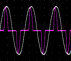
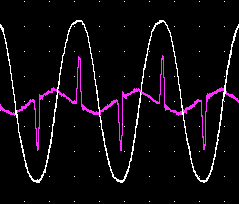
To correct power factor for a device like this by adding an external device across the line, the way capacitors have traditionally been used to correct power factor for motors, would mean fielding a device that drew power near the zero crossings, and fed it back into the line near the peaks. Such a device could be built, but would be much more complicated, expensive, inefficient, and unreliable than a capacitor. It is probably easier to demand that the devices being powered be power factor corrected, as are many modern computer power supplies, such as the one that produced the following scope traces – the first, again, when running, and the second when quiescent:
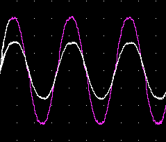
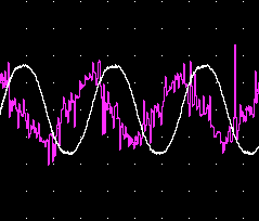
(As can be seen, the power factor correction only applies when the power supply is on; when it is quiescent, the small current it draws looks a lot like the current a capacitor would draw: about 90 degree phase lead. Indeed, that current is likely being drawn by a filtering capacitor inside the unit, such as is often placed across the input for the purpose of blunting power surges and suppressing RF emissions.)
It’s not just when a device consumes power in a nontraditional way that it is difficult to correct power factor; it also is difficult when a device provides power in a nontraditional way – that is, as something other than a sine wave. The usual nonsinusoidal power waveform is what marketing people have decided to call a “modified sine wave”, which really would be better termed a modified square wave. Whereas a square wave of 115VAC would alternate between 115V and -115V, the modified square wave alternates zero, 162V, zero, -162V:
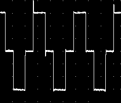
That peak voltage is chosen to be the same as the peak voltage of a sine wave with RMS voltage 115V; the time spent at zero volts is chosen so that the signal as a whole is 115V RMS. This is the waveform output by most inverters – inverters being devices for converting DC, usually at 12V or 24V, into alternating current at line voltage. Most uninterruptible power supplies dish out the same sort of modified square wave when running off battery power. If a motor is driven by such a voltage source, it will have a lagging power factor; but if one were to try to correct it by adding a capacitor, at the sudden transitions between voltages the capacitor would try to draw enormous currents. Rather than correcting the power factor, that would dramatically worsen it – if, indeed, the inverter didn’t shut itself off instantly, as it probably would in self-defense when it detected those enormous currents.
Nevertheless, modified square waves have their upsides, as regards power factor. The old computer power supply that yielded the first graphs above, I measured drawing 219W and 313VA on AC power from the utility (a power factor of 0.70). On an inverter, with the same load, it drew 207W and 240 VA (a power factor of 0.86); the current waveform looked like this:
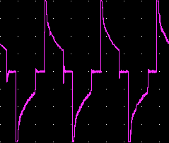
The fact that this power supply draws current only near the peaks makes for a better power factor on the inverter, since its voltage waveform has wider peaks. Also, it improves the power supply’s internal efficiency a bit, so it draws less real power.
On the other hand, the same power supply also has a small filtering capacitor across its input, to help deal with power surges and to suppress RF emissions. With the power supply quiescent, it draws 2 watts at 8 VA from the AC line, but draws something like 75 VA from the inverter (though that measurement is quite imprecise, since the wattmeter I was using couldn’t really resolve the current spikes). The power-factor-corrected power supply graphed above behaved even worse on the inverter when quiescent, drawing about 90 VA; even when switched off using the switch on the back of the power supply (which turns off the current to every part of it that is at all active, leaving only a filtering capacitor or two drawing power), it drew about 60 VA. Yet under load, its behavior was again good: 264 W at 287 VA, a power factor of 0.90, although it still shows current spikes:
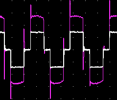
So although power factor is usually specified as just a single number (or as a function of load), really those numbers apply only to sinusoidal voltage waveforms, and can’t be extrapolated to other waveforms.